Design category for installations and structures modelled with Autodesk Inventor Frame Generator:
metal frames, support structures, access frames, technical furniture skeletons, railing supports and workshop-ready supplier coordination.
FRM
Metal Frame Installations
Structural or semi-structural frames used for interior installations, technical supports and custom-built assemblies.
Rectangular tube and profile frames
Skeleton-model based design
Frame member placement and alignment
Supplier coordination package
SUP
Support Structures
Support frames for equipment, cabinets, panels, technical furniture or installation zones.
Equipment support frames
Wall or floor fixing concepts
Bolted/welded coordination
Workshop discussion drawings
RAIL
Railing & Guard Support Frames
Frame-generator-based support logic for garde-corps, railings, grilles and access barriers.
Post and rail frame logic
Profile selection
End treatments and mitres
Fixing-plate coordination
CAB
Technical Cabinet Skeletons
Internal metal skeletons for technical cabinets, AV furniture, media walls and access-panel systems.
Frame skeleton modelling
Access and service zones
Glass/panel support frames
Interior design coordination
GATE
Doors, Gates & Access Frames
Metal frame design for gates, hinged frames, technical access doors and controlled-entry structures.
Hinge-side frame logic
Lock/cylinder preparation zones
Frame squareness and alignment
Installation notes for supplier
DOC
Manufacturer Coordination
Client-readable design first, then supplier-focused drawings and files for the selected workshop or installer.
Dimensions and frame member summary
Profile/material selection
Manufacturing questions
Installation coordination notes
Frame Generator workflow
Autodesk Inventor Frame Generator is useful when the installation is built from repeated structural members:
tubes, angles, channels, beams, rails and support profiles. The workflow usually starts from a 2D/3D skeleton,
then frame members are placed along sketch lines or model edges.
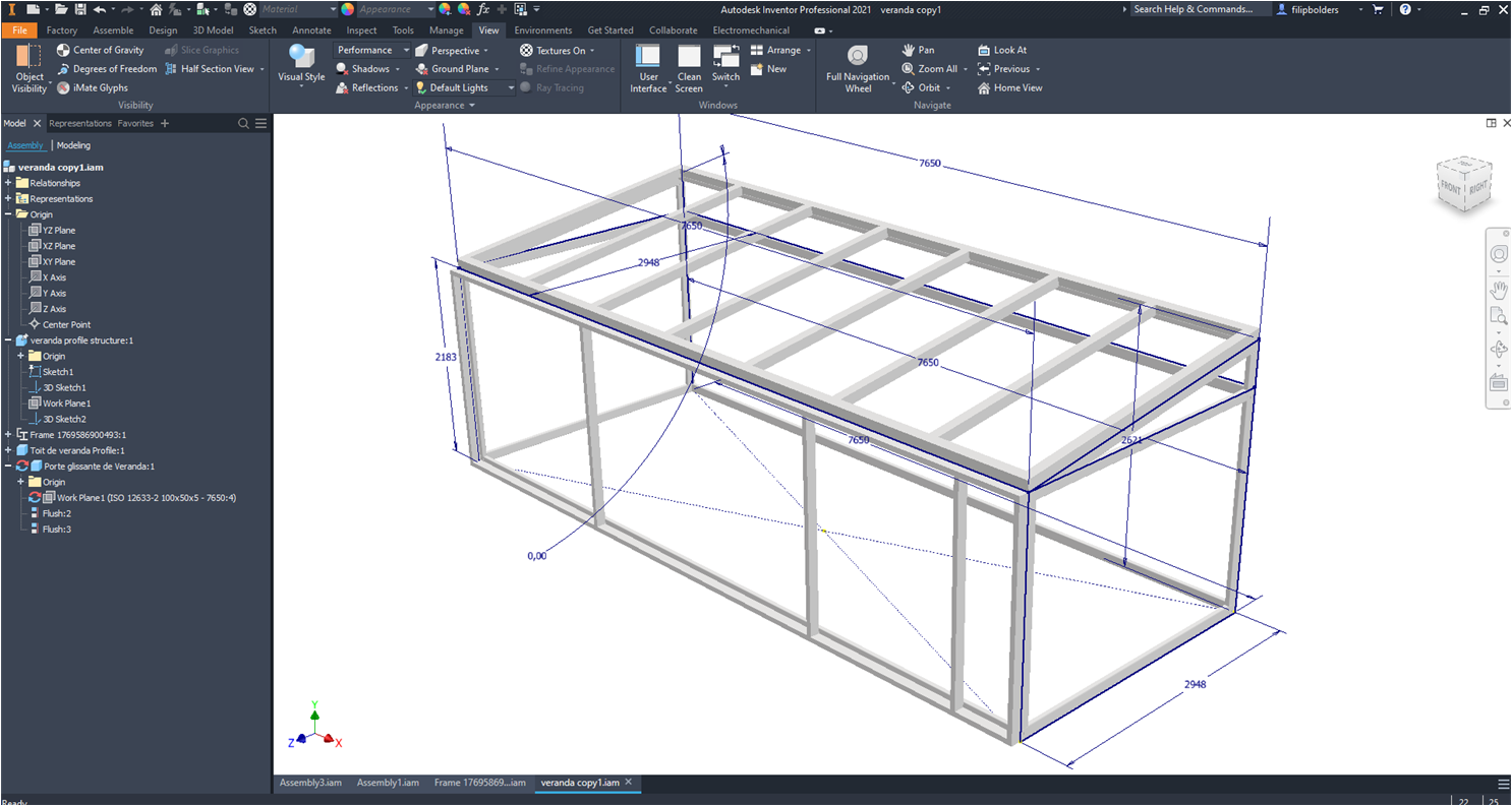
Real project-style Inventor assembly screenshots can be added here to show the Frame Generator workflow:
reference skeleton, frame-member assembly, profile list and 3D installation model.
Screenshot area prepared for a non-NDA Autodesk Inventor Frame Generator assembly detail.
The preview should show a non-confidential frame assembly only: no client names, no protected title blocks,
no supplier-private production data.
Public website pages show the design category and coordination process. Production-level frame drawings and supplier files are normally exchanged directly
with the selected workshop, metalwork company, installer or manufacturer.